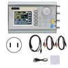
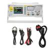
Feature:
1. Function signal generator, dual‑channel design, 200MSa s sampling rate, 30MHz output frequency.
2. Support arbitrary waveform, sine waves, square waves, ramp waves, pulse waves, noise, DC, arbitrary waveform.
3. The function buttons are complete, and the modulation settings can be made through these buttons.
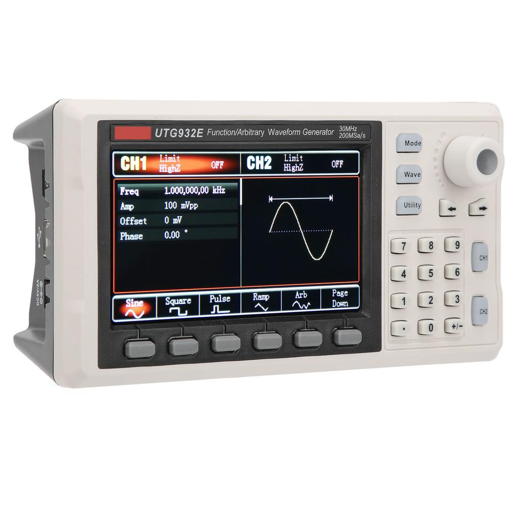
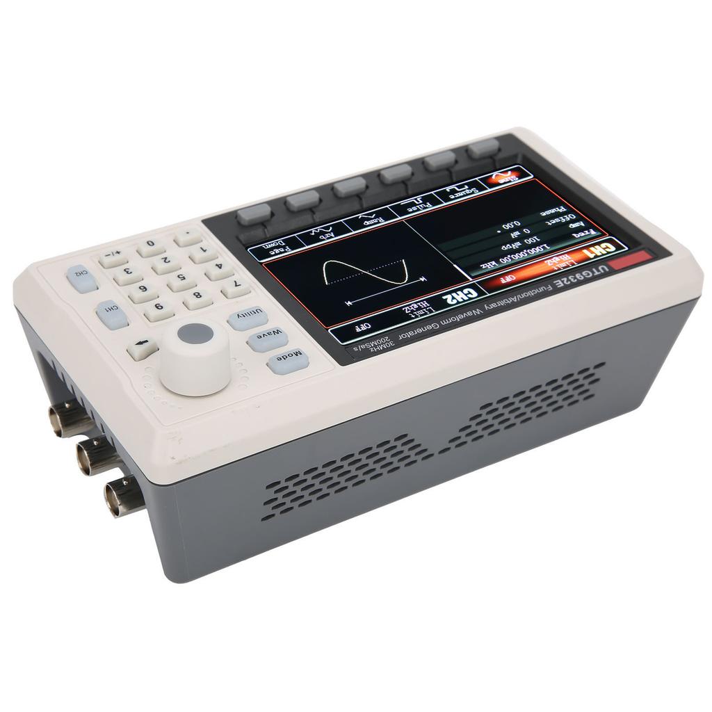
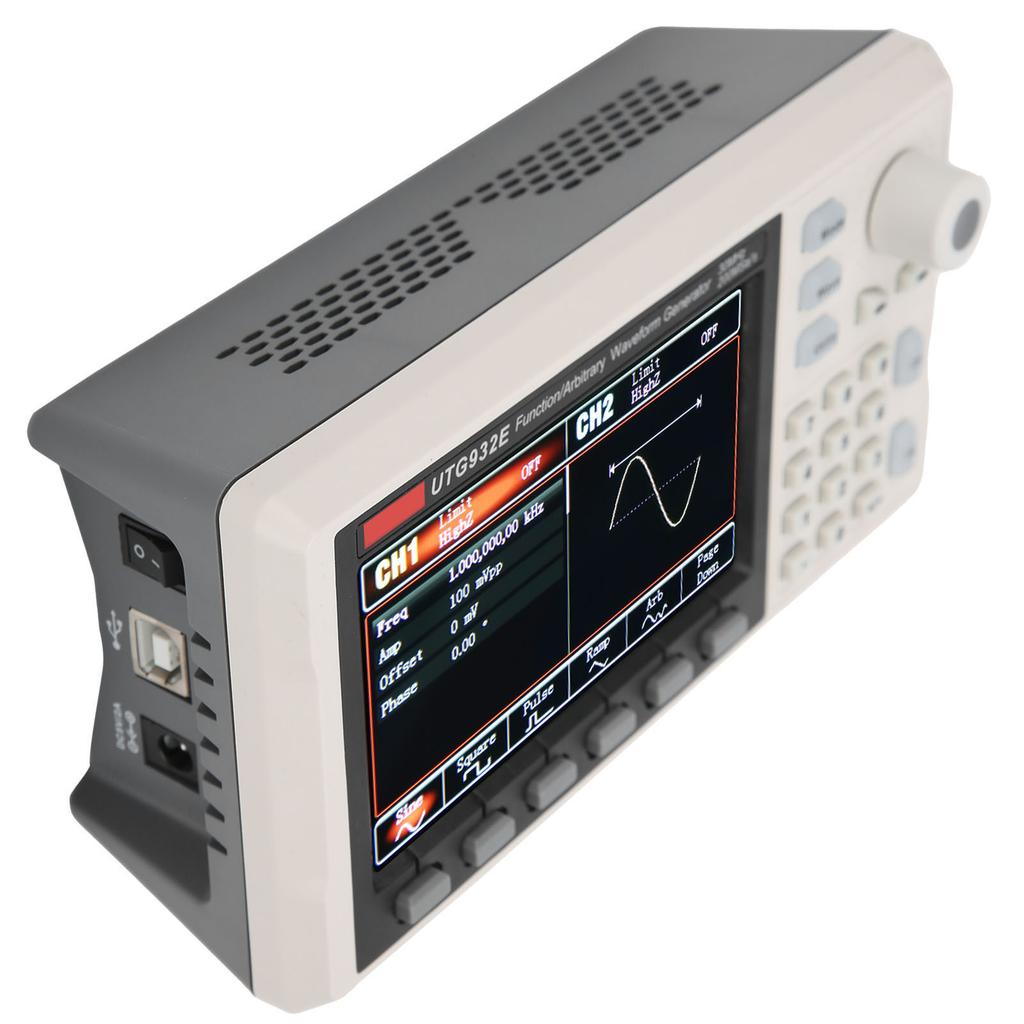
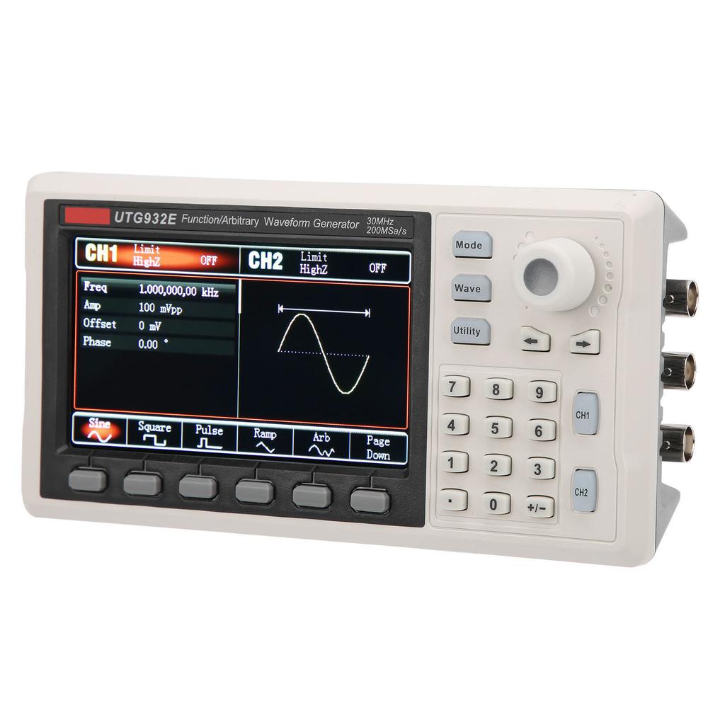
4. With 4.3in high‑resolution TFT LCD screen, distinguish output status of channel 1 and channel 2, function menus and other important information.
5. Accurate measurement, concise, intuitive, and easy to operate. It is widely used in electronics enthusiasts and scientific research institutions.
Specification:
Item Type: Function Generator
Material: ABS
Display Type: 4.3in TFT LCD
Display Resolution: 480 Horizontal x 272 Vertical
Product Voltage: DC5V, 2A
Power Consumption: Less Than 10W
Operating Temperature Range: 10 celsius +40 celsius , Non Operating Temperature Range: 20 celsius +60 celsius
Cooling Method: Natural Cooling
Humidity Range:
Below +35 celsius : less than 90percent Relative Humidity
+35 celsius +40 celsius : less than 60percent Relative Humidity
Altitude: Below 2000 meters for operation, below 15000 meters for non operation
Product Size: Approx. 172x68x90mm 6.8x2.7x3.5in
Technical Index
Function Name
Work performance
Aisle
2 channels
Highest Frequency
30MHz
Sampling Rate
200MSa s
Waves
Sine waves, square waves, ramp waves, pulse waves, noise, DC DC, arbitrary waveform
Operating Mode
Output strobe, continuous, modulation, frequency sweep
Modulation Type
AM, FM, PM, FSK, Line, Log
Sine Waves
Frequency Range
1One millionth Hz 30MHz
Resolution
1One millionth Hz
Accuracy
+ 50ppm within 90 days, + 100ppm within 1 year (18 degrees C to 28 degrees C)
Harmonic Distortion (Typical Value)
Test condition: output power 0dBm
DC 5MHz 60dBc
5MHz 30MHz 50dBc
30MHz 60MHz 40dBc
Total Harmonic Distortion (Typical Value)
<0.2percent (DC 20kHz, 1Vpp)
Spurious Signal (Non Harmonic, Typical Value)
Test condition: output power 0dBm
DC 10MHz,< 70dBc
more than 10MHz less than 70dBc+6dB Octave
Phase Noise (Typical Value)
10MHz: less than 125dBc Hz (typical value, 0dBm, 10kHz offset)
Square Waves
Frequency Range
1uHz 15MHz
Resolution
1uHz
Rise Fall Time
less than 50ns (typical value, 1kHz, 1Vpp)
Overshoot (Typical Value)
less than 2percent
Symmetric (Under 50percent Duty Cycle)
1ns+100ppm of period
Shake (Typical Value)
Typical value (1MHz, 1Vpp, 50 Ohm )
less than 5MHz: 2ppm+200ps
more than 5MHz:200ps
Slope
Frequency Range
1uHz 400kHz
Resolution
1uHz
Non Linearity
3percent + 2mV (typical value, 1kHz, 1Vpp, symmetric 50percent )
Symmetric
0.0percent to 100.0percent
Pulse Waves
Frequency Range
1One millionth Hz 15MHz
Resolution
1uHz
Pulse Width
more than 22ns
Variable Edge
15ns 8s
Overshoot (Typical Value)
less than 2percent (typical value 1Vpp)
Shake
150ps
Gaussian Noise
Bandwidth
30MHz bandwidth ( 3dB) (typical value)
DC Offset
Range (Peak AC+DC)
+ 5V (50 Ohm )
+ 10V (High Resistance)
Offset Accuracy
+ 3percent of offset setting value, + 1.5percent of amplitude setting value+ 2mV
Arbitrary Waveform Characteristics
Frequency Range
1One millionth Hz 10MHz
Resolution
1uHz
Waves Length
4kpts
Vertical Resolution
14bits (including compliance)
Sampling Rate
200MSa s
Minimum Rise Fall Time
less than 20ns typical value
Shake
5ns+ 150ps
Non Volatile Storage
24 waveforms
Output Characteristics
Amplitude Range
less than 10MHz: 1mVpp 10Vpp; (50 Ohm )
less than 60MHz: 1mVpp 5Vpp; (50 Ohm )
Accuracy (1kHz Sine Waves)
+ (3percent of setting value + 2mVpp)
Amplitude Flatness (Relative to 1kHz sine waves, 1Vpp 50 Ohm )
Test condition: typical value (sine waves, 2.0Vpp)
less than 100kHz: + 0.1dB
less than 20MHz: + 0.2dB
less than 30MHz: + 0.4dB
less than 40MHz: + 0.5dB
less than 60MHz: + 0.8dB
Waves Output
Impedance
50 Ohm typical
Insulation
Maximum 42Vpk to ground
Protection
Channel protection
AM Modulation
Carrier
Sine, square waves, oblique waves, arbitrary waves
Modulation Waves
Sine, square waves, ramp waves, noise, arbitrary waves
Modulation Frequency
2MHZ 200KHZ
Modulation Depth
0percent 120percent
FM Modulation
Carrier
Sine, square waves, oblique waves, arbitrary waves
Modulation Waves
Sine, square waves, ramp waves, noise, arbitrary waves
Modulation Frequency
1uHZ 200KHZ
Frequency Deviation
DC 15MHZ
Pm Modulation
Carrier
Sine, square waves, oblique waves, arbitrary waves
Modulation Waves
Sine, square waves, ramp waves, noise, arbitrary waves
Modulation Frequency
2mhz 200khz
Deviation
0 degrees 360 degrees
FSK Modulation
Carrier
Sine, square waves, oblique waves, arbitrary waves
Source
Internal external
Modulation Waves
Square waves with 50percent duty cycle
Rate
2MHZ 100KHZ
Sweep
Carrier
Sine, square waves, oblique waves, arbitrary waves
Types of
Linear, logarithmic
Sweep Time
1ms 500s+ 0.1percent
Sync Signal
Output Level
TTL compatible
Output Frequency
1One millionth Hz 2MHz
Output Impedance
50 Ohm , typical value
Coupling Method
Direct current
Trigger Input
Input Level
TTL compatible
Input Resistance
more than 10k Ohm , DC coupling
Frequency Meter
Input Level
TTL compatible
Input Frequency Range
100mHz 100mHz
Accuracy
+ 51ppm
Frequency Resolution
7 bit
Coupling Method
Direct current
.How to Use:
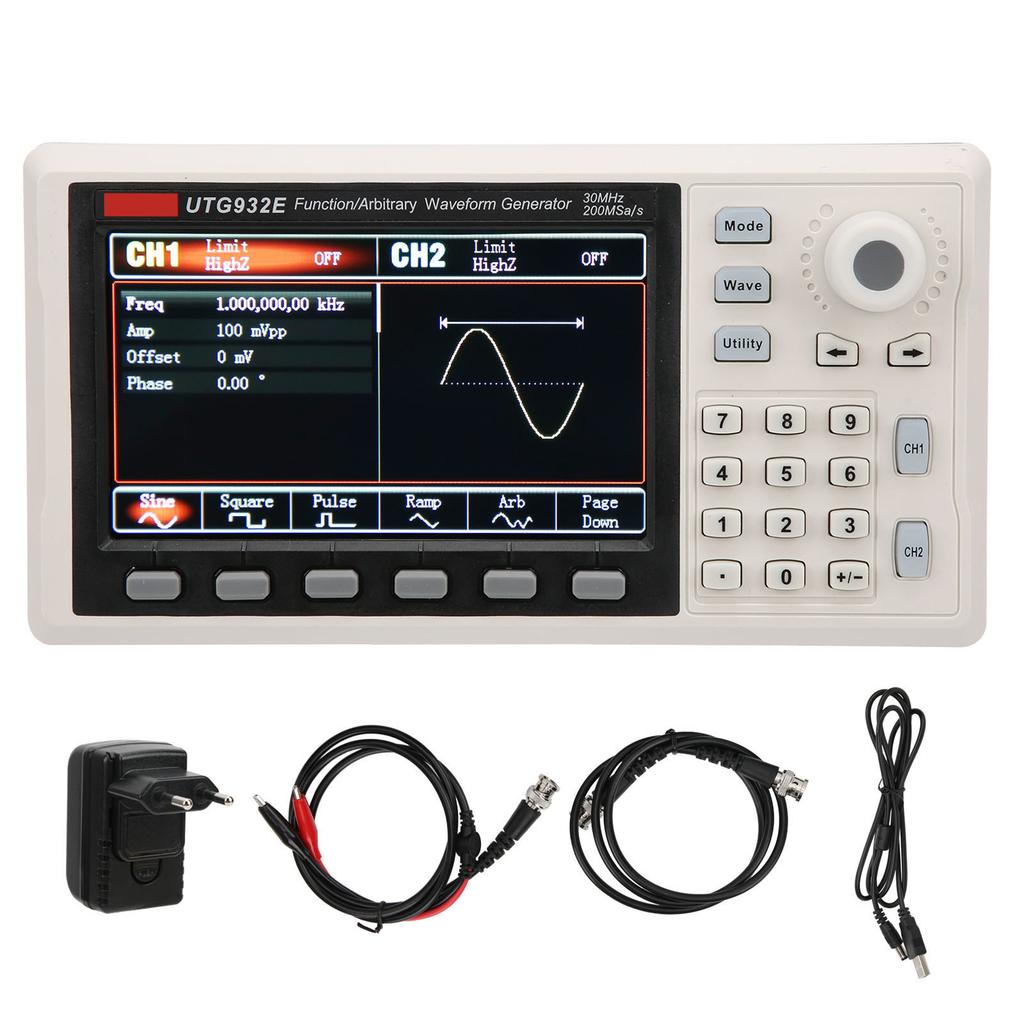
1. Display
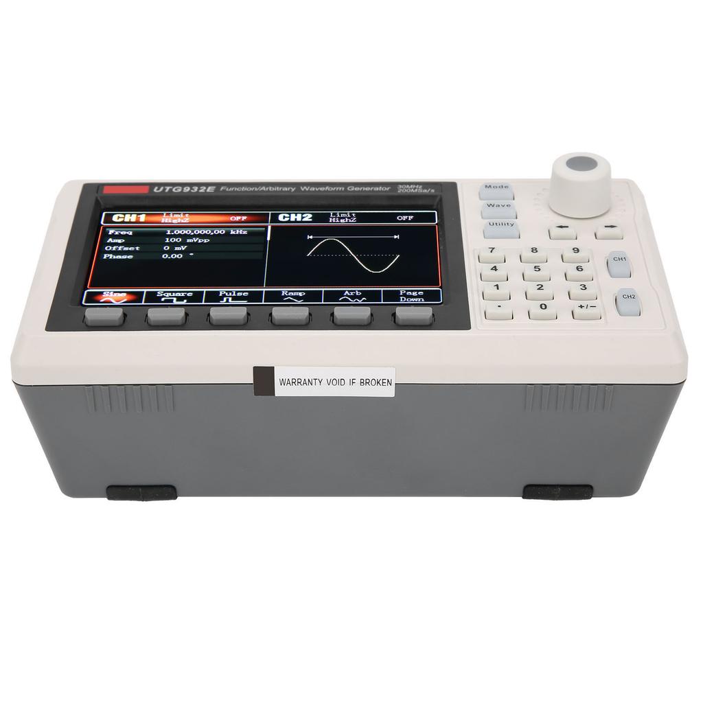
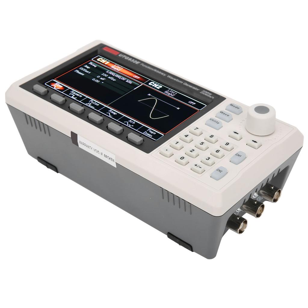
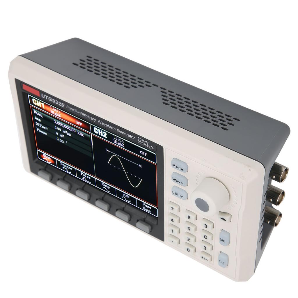
4.3in high resolution TFT color screen, clearly distinguishes the output status, function menus and other important information of channel 1 and channel 2, and the user friendly system interface makes human computer interaction easier and improves your work efficiency.
2. Function buttons
The function buttons are Mode, Waves, Utility, through these buttons for modulation settings, fundamental waves selection and auxiliary function settings, etc.
3. Multi function knob button
Rotate the multi function knob to change the number (turn clockwise to increase the number) or use it as a direction key, press the multi function knob to select functions or determine the set parameters
4. Direction keys
When using the multifunction knob and direction keys to set parameters, it is used to switch the digit of the number or clear the previous digit currently input or move (left or right) the position of the cursor
5.CH1 2 control output key
Quickly switch the current channel displayed on the screen (CH1 information label is highlighted as the current channel, at this time the parameter list displays channel 1 related information, so that the waveform parameters of channel 1 can be set). If channel one is the current channel (CH1 information label is highlighted), you can quickly turn on off the channel one output by pressing the CH1 key, or you can press the Utility key to popup the label and then press the channel one setting soft key to set. When the channel output is turned on, the backlight is on, and the output function mode (waveform or modulation or linear or logarithmic ) will be displayed in the information label, and the output terminal will output the signal. When it is off, the CH1 key or CH2 button, the backlight is off, and the information label will display OFF at the same time, and the output terminal will be turned off at the same time.
6. Numeric keypad
Number keys 0 9, decimal point . , sign key + for inputting the required parameters. The left direction key backspaces and clears the previous digit of the current input
7. Menu operation soft keys
Select or view the contents of the label (located at the bottom of the function interface) corresponding to the label of the soft key, and set the parameters with the numeric keyboard or multi function knob or direction keys.
Package List:
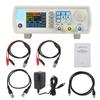
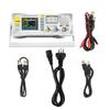
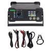
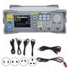
1 x Function Generator1 x Adapter1 x Converter1 x Power Line1 x Testing Clip1 x 2 Way Device1 x Operation Guide
Note:
1. Please allow 0‑1 inch error due to manual measurement. Thanks for your understanding.2. Monitors are not calibrated same, item color displayed in photos may be showing slightly different from the real object. Please take the real one as standard.



 Rimborso per mancata consegna